Blog
CamBam
PCB Isolation Routing
CNC
Mk I (smasher)
Frame
Linear guides
Leadscrew drive
Motors and controller
Improvements
CNC Software
Gallery
Touch Probe
CNC Links
Links
Contact
Homemade CNC Router / Mill
Linear Guides
I had inherited and dimembered a couple of old large industrial dotmatrix printers. These provided (what I thought of at the time) as a bounty of metal rods, steppers, sensors and servo motors. On hind sight, I probably would have been better off, ebaying the printers and then buying exactly what I wanted with the proceeds. Ho Hum.
The largest silver steel rods were 17.9mm diam and 500mm long. I thought these more than adequate at the time but these could certainly do with beefing up and or supporting.
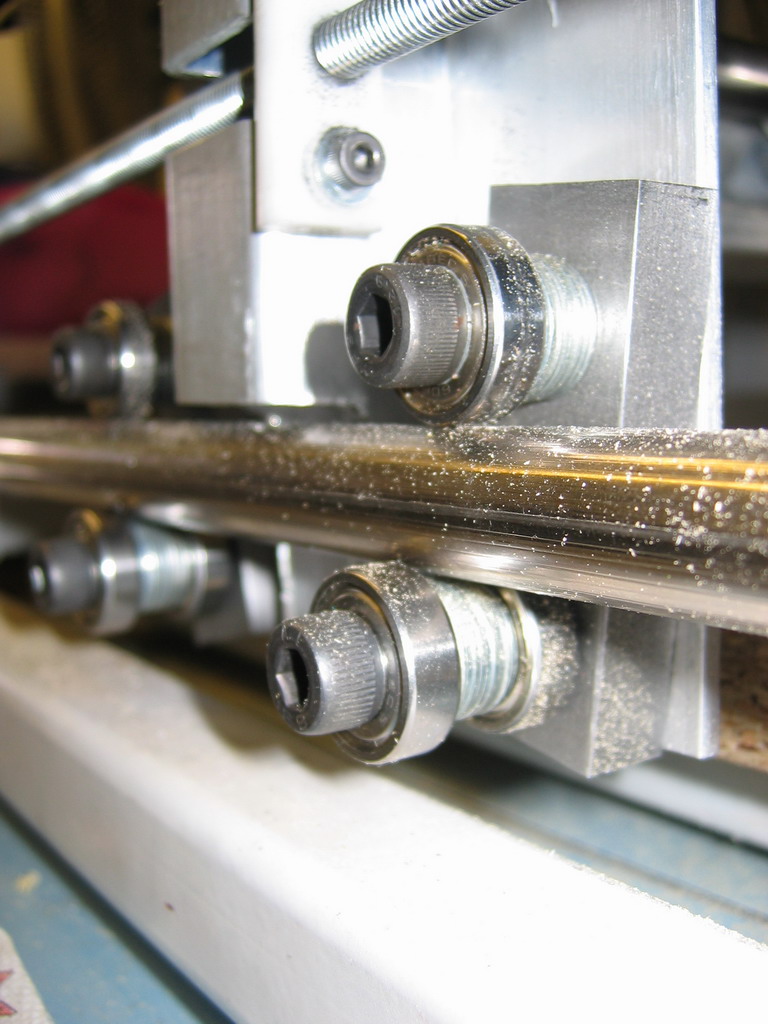
The X axis makes use of bronze bushings from the dot matrix printer heads. The 2 printers were similar but not identical so I had much fun and games securely mounting the bushings to a carriage plate and keeping them as parallel as possible. Again, with the benefit of hindsight I should have gone with roller bearings, similar to the Y axis. The bushings do work, but were very unforgiving of any misalignment and are quite stiff which detracts from the maximum speed that I can drive the thing.
The Y axis bearings I am very pleased with. Faced with the challenge of mounting 3 bearings radially around the printer rod with limited tools, in the end, out of desperation I came up with a very simple 'temporary' arrangement that would hopefully hold together long enough to get the machine working, then use the machine to make something more sophisticated. The bearing blocks consist of a 1" x 0.5" steel block with 2 x M8 tapped holes spaced a considered distance apart and a central mounting hole. A 608 skate bearing is bolted to one hole and another pair of bearings bolted to the other. All the bearings are spaced a set distance apart using washers. I had intended to turn some spacers on the lathe but the washers were fine. The single bearing rides on top of the rail as is a bearings want. So far so good. The lower pair run against the underside of the rod, but these run against the inner rims of the bearing. This is not ideal for a number of reasons. Skate bearings are not designed to cope with much thrust and the more thrust on them, the more friction they produce. It presumeably doesn't do their welfare much good either. The other downer is that the rims have a small area of contact with the rod which causes a groove to be pressed into the rod.
But when the thing was all assembled and adjusted (much more easily than the X axis), I started to realise this bearing arrangment might be more permanent than I thought. After a short while, the lower bearings 'bedded in' to the rod. The grooved rod presents much more contact area on the bearing. The groove doesn't appear to be getting any deeper and also helps prevent lateral movement of the carriage.
The mounting and adjustment of the Y axis bearing block is simplicity itself, comprising of one M8 bolt. The mounting hole in the gantry is slightly oversized, allowing a small amount of adjustment up and down. The steel block can also rotate about the mounting bolt so that the upper and lower bearings can be rotated until they contact the rod.